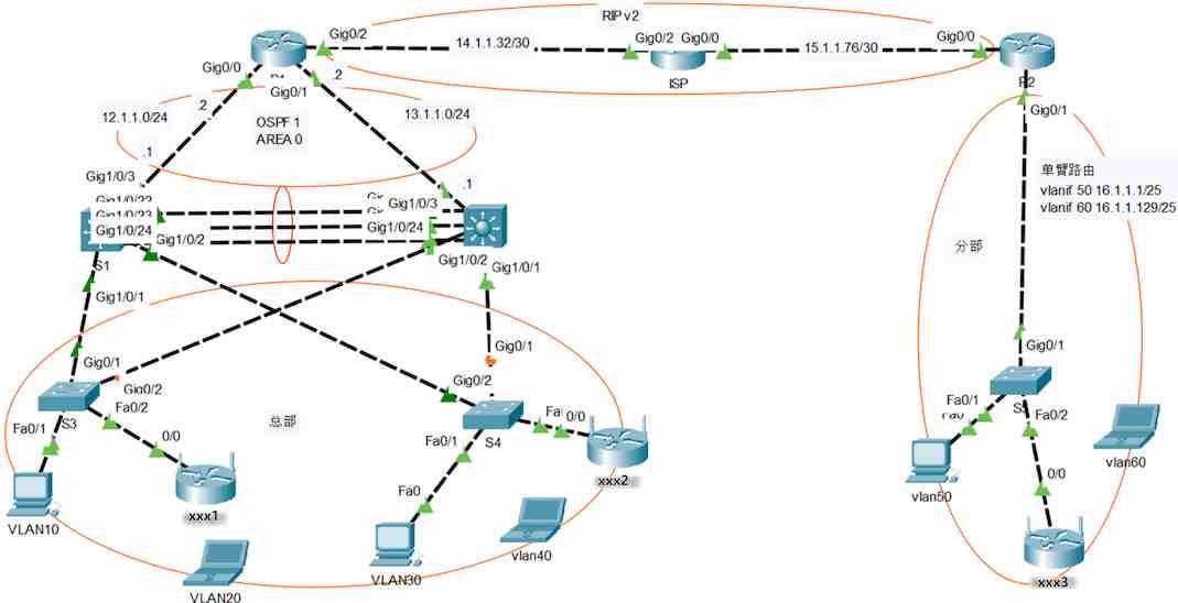
题目 网络拓扑图
设备连接与 IP 地址规划表
设备名
接口
IP地址
对端设备
接口
IP地址
S1
G1/0/1
无
S3
G0/1
无
S1
G1/0/2
无
S4
G0/2
无
S1
G1/0/22
无
S2
G1/0/22
无
S1
G1/0/23
无
S2
G1/0/23
无
S1
G1/0/24
无
S2
G1/0/24
无
S1
G1/0/3
12.1.1.1/24
R1
G0/0
12.1.1.2/24
S2
G1/0/1
无
S4
G0/1
无
S2
G1/0/2
无
S3
G0/2
无
S2
G1/0/3
13.1.1.1/24
R1
G0/1
13.1.1.2/24
R1
G0/2
14.1.1.33/30
ISP1
G0/2
需计算
ISP
G0/0
需计算
R2
G0/0
15.1.1.78/30
R2
G0/1.50
16.1.1.1/25
S5
G0/1
无
R2
G0/1.60
16.1.1.129/25
S5
G0/1
无
任务书
根据拓扑图中设备名修改主机名,根据《设备连接与IP地址规划表》配置相应接口的IP地址。
VTP配置:使用VTP技术创建VLAN:以S1为服务器模式,S2\S3\S4为客户模式域名为xxx.com,密码为security;
链路聚合配置:为避免单点故障,提高网络的可靠性,增加网络带宽,在S1和S2上配置链路聚合,使用动态LACP聚合模式。
生成树配置:为避免总部网络中形成环路,加快网络收敛速度,需要配置相应的生成树协议,其中S1为根桥,S2为备用根用,并在网络中相应的交换机接口开启根保护功能,通过相应的配置加快链路的收敛,保护bpdu。
VLAN及配置接口:分部VLAN配置,并完成所有接口VLAN的添加。
可变长子网掩码:网络内部使用192.168.99.0/24网段,每个VLAN均为一个独立网段,平均分配IP地址。每段中的最后2和第3个可用IP分别分配给S1和S2中的对应VLANIF接口做为网关地址。
HSRP配置:为保证网络的可靠性,在S1和S2配置热备份路由协议,对应虚拟路由器VLAN使用每个子网中的第1个可用IP。其中S1中各VLAN的优先级为110,S2上的使用默认优先级,两台交换机的VLAN均启用抢占模式并跟踪相应接口。
802.1X配置:配置无线路由器,SSID分别为拓扑中无线路由器名称,使用WPA2-PSK认证方式,密码为a1234567,加密方式为AES。路由器Internet接口IP为该子网中的最一个可用IP,路由器内部地址网段为192.168.vlanID.0/24,笔记本获取到IP后可以正常PING通各自网关。
RIP配置:R1,ISP,R2配置RIPv2,发布各个相关网段,使各路由器之间能相互网络连通。
OSPF配置:根据拓扑要求,在相关设备上配置OSPF协议,进程号为1,其中S1的Router-id为1.1.1.1, S2的Router-id为2.2.2.2,区域为0,发布相应网段。
单臂路由配置:在分部通过单臂路由的配置,实现分部两个VLAN的数据交互与连通。
NAT配置:在分部路由器上配置NAT,使分部路由器出口IP为转换后的访问地址,以隐藏分部内网地址,增强网络安全。
路由重发布配置:在R1中配置路由重发布,以便全网能够正确通信。
题解
路由器使用2911模拟,三层交换机使用3650-24PS(需要添加AC-POWER-SUPPLY供电模块)模拟,二层交换机使用2921模拟,无线路由器使用WRT300N模拟。
根据拓扑图中设备名修改主机名 ,根据《设备连接与IP地址规划表》配置相应接口的IP地址 。
R1
1
2
3
4
5
6
7
8
9
10
11
12
conf t hostname R1 int g0/0 ip add 12.1 .1 .2 255.255 .255 .0 no sh int g0/1 ip add 13.1 .1 .2 255.255 .255 .0 no sh int g0/2 ip add 14.1 .1 .33 255.255 .255 .252 no sh
ISP
1
2
3
4
5
6
7
8
9
conf t hostnamee ISP int g0/2 ip add 14.1 .1 .34 255.255 .255 .252 no sh int g0/0 ip add 15.1 .1 .77 255.255 .255 .252 no sh
R2
1
2
3
4
5
6
7
8
9
10
11
12
13
14
15
16
conf t hostnamee R2 int g0/0 ip add 15.1 .1 .78 255.255 .255 .252 no sh int g0/1 no sh int g0/1.50 encapsulation dot1Q 50 ip add 16.1 .1 .1 255.255 .255 .128 int g0/1.60 encapsulation dot1Q 60 ip add 16.1 .1 .129 255.255 .255 .128
S1
1
2
3
4
5
6
7
8
9
10
11
12
13
14
15
16
17
conf t hostname S1 int g1/0 /3 no switchport ip add 12.1 .1 .1 255.255 .255 .0 no sh int range g1/0 /1 -2 switchport trunk encapsulation dot1q switchport mode trunk int range g1/0 /22 -24 switchport trunk encapsulation dot1q switchport mode trunk
S2
1
2
3
4
5
6
7
8
9
10
11
12
13
14
15
16
conf t hostname S2 int g1/0 /3 no switchport ip add 13.1 .1 .1 255.255 .255 .0 no sh int range g1/0 /1 -2 switchport trunk encapsulation dot1q switchport mode trunk int range g1/0 /22 -24 switchport trunk encapsulation dot1q switchport mode trunk
S3
1
2
3
4
5
6
7
8
9
10
11
12
13
conf t hostname S3 int range g0/1 -2 switchport mode trunk int f0/1 switchport access vlan 10 int f0/2 switchport access vlan 20
S4
1
2
3
4
5
6
7
8
9
10
11
12
13
conf t hostname S4 int range g0/1 -2 switchport mode trunk int f0/1 switchport access vlan 30 int f0/2 switchport access vlan 40
S5
1
2
3
4
5
6
conf t hostname S5 int g0/1 switchport mode trunk
注意:S3和S4连接无线路由器 的端口必须使用ACCESS类型,否则无线设备将无法与vlan网关通信。
VTP 配置:使用VTP技术创建VLAN:以S1为服务器模式,S2\S3\S4为客户模式, 域名为xxx.com,密码为security。
S1
1
2
3
4
5
6
7
8
9
10
11
12
13
14
15
conf t vtp domain xxx.com vtp password security vlan 10 vlan 20 vlan 30 vlan 40 do show vlan briefdo show vtp statusdo show vtp password
S2、S3、S4
1
2
3
4
5
conf t vtp domain xxx.com vtp password security vtp mode client
注意:
链路聚合 配置:为避免单点故障,提高网络的可靠性,增加网络带宽,在S1和S2上配置链路聚合,使用动态LACP聚合模式。
S1、S2
1
2
3
4
5
6
7
8
9
10
11
12
en conf t int port-channel 1 int range g1/0 /22 -24 channel-protocol lacp channel-group 1 mode active switchport trunk encapsulation dot1q switchport mode trunk do show etherchannel summary
注意:LACP协议的聚合模式需使用动态(active)聚合。
生成树 配置:为避免总部网络中形成环路,加快网络收敛速度,需要配置相应的生成树协议,其中S1为根桥 ,S2为备用根桥 ,并在网络中相应的交换机接口开启根保护功能,通过相应的配置加快链路的收敛,保护bpdu。
S1
1
2
3
4
5
6
7
8
9
10
11
12
en conf t spanning-tree mode rapid-pvst spanning-tree vlan 10 ,20 ,30 ,40 root primary int range g1/0 /1 -2 spanning-tree guard root int range g1/0 /22 -24 spanning-tree guard root
S2
1
2
3
4
5
en conf t spanning-tree mode rapid-pvst spanning-tree vlan 10 ,20 ,30 ,40 root secondary
S3
1
2
3
4
5
6
7
8
9
10
en conf t spanning-tree mode rapid-pvst int f0/1 -2 int range f0/1 -2 spanning-tree portfast spanning-tree bpduguard enable
S4
1
2
3
4
5
6
7
8
9
en conf t spanning-tree mode rapid-pvst int f0/1 -2 int range f0/1 -2 spanning-tree portfast spanning-tree bpduguard enable
注意:
思科交换机默认开启IEEE STP功能,为了满足加快网络收敛速度的要求,需要切换为rapid-pvst(快速生成树)模式。
根防护功能强制接口成为指定端口(防止指定端口成为根端口),以消除新接入的交换机成为根交换机的可能。
配置了bpdu保护功能的接口如果收到吧bpdu数据包,交换机将立即将该接口置为非活跃状态(errdisable状态)。这是一种防护机制,可以防止非法的生成树信息进入网络导致环路,并确保网络的稳定性和安全性。
验证:
VLAN 及配置接口:分部 VLAN配置,并完成所有接口VLAN的添加。
S5
1
2
3
4
5
6
7
8
9
10
11
12
en conf t vlan 50 vlan 60 int f0/1 switchport access vlan 50 int f0/2 switchport access vlan 60
可变长子网掩码 :网络内部使用192.168.99.0/24网段,每个VLAN均为一个独立网段,平均分配 IP地址。每段中的最后2和第3个可用IP分别分配给S1和S2中的对应VLANIF接口做为网关地址。
S1
1
2
3
4
5
6
7
8
9
10
11
12
13
14
15
16
17
en conf t ip routing interface vlan10 ip address 192.168 .99 .61 255.255 .255 .192 interface vlan20 ip address 192.168 .99 .125 255.255 .255 .192 interface vlan30 ip address 192.168 .99 .189 255.255 .255 .192 interface vlan40 ip address 192.168 .99 .253 255.255 .255 .192
S2
1
2
3
4
5
6
7
8
9
10
11
12
13
14
15
16
en conf t ip routing interface vlan10 ip address 192.168 .99 .60 255.255 .255 .192 interface vlan20 ip address 192.168 .99 .124 255.255 .255 .192 interface vlan30 ip address 192.168 .99 .188 255.255 .255 .192 interface vlan40 ip address 192.168 .99 .252 255.255 .255 .192
注意:
题目说使用变长子网掩码VLSM (不可能平均分配),又说平均分配 IP地址,前后表达不一致,但稍微分析可知使用的还是定长子网掩码FLSM (可平均分配地址),即每个网段都使用/26的掩码。
“每段中的最后2和第3个可用IP分别分配给S1和S2中的对应VLANIF接口做为网关地址”:最后2和第3个可用IP地址 也就是每个网段的倒数第2个和倒数第3个可用地址 (倒数第1的可用地址被第8题 要求留给无线路由器使用),例如vlan10的可用地址范围为192.168.99.1-192.168.99.62,那么倒数第2个可用地址为192.168.99.61,倒数第3个可用地址为192.168.99.60,所以S1和S2的vlan 10的网关地址分别为192.168.99.61和192.168.99.60。之所以会要求分别设置IP地址,是为了给下一题的双机热备份HSRP 做铺垫 。
验证:
HSRP配置:为保证网络的可靠性,在S1和S2配置热备份 路由协议,对应虚拟路由器VLAN使用每个子网中的第1个可用IP。其中S1中各VLAN的优先级为110,S2上的使用默认优先级,两台交换机的VLAN均启用抢占模式并跟踪相应接口。
S1
1
2
3
4
5
6
7
8
9
10
11
12
13
14
15
16
17
18
19
20
21
22
23
24
25
26
en conf t int vlan 10 standby 1 ip 192.168 .99 .1 standby 1 priority 110 standby 1 preempt int vlan 20 standby 1 ip 192.168 .99 .65 standby 1 priority 110 standby 1 preempt int vlan 30 standby 1 ip 192.168 .99 .129 standby 1 priority 110 standby 1 preempt int vlan 40 standby 1 ip 192.168 .99 .193 standby 1 priority 110 standby 1 preempt do show standby brief
S2
1
2
3
4
5
6
7
8
9
10
11
12
13
14
15
16
17
18
19
20
en conf t int vlan 10 standby 1 ip 192.168 .99 .1 standby 1 preempt int vlan 20 standby 1 ip 192.168 .99 .65 standby 1 preempt int vlan 30 standby 1 ip 192.168 .99 .129 standby 1 preempt int vlan 40 standby 1 ip 192.168 .99 .193 standby 1 preempt do show standby brief
验证:
S1交换机的各vlan优先级为110并成为活动(Active)路由器, 同时可见备份(Standby)路由器的IP地址为S2的各vlan的IP:
S2交换机成为备份(Standby)路由器, 同时可见活动(Active)路由器的IP地址为S1的各vlan的IP:
802.1X配置:配置无线路由器 ,SSID分别为拓扑中无线路由器名称,使用WPA2-PSK认证方式,密码为a1234567,加密方式为AES。路由器Internet接口IP为该子网中的最一个可用IP ,路由器内部地址网段为192.168.vlanID.0/24,笔记本获取到IP后可以正常PING通各自网关。
注意:
GUI配置…
验证:
vlan20笔记本可以获取到IP地址,并PING通无线路由器(其他笔记本操作一致故不再重复演示):
RIP配置:R1,ISP,R2配置RIPv2 ,发布各个相关网段,使各路由器之间能相互网络连通。
R1
1
2
3
4
5
6
7
8
9
en conf t router rip version 2 no auto -summary network 14.1 .1 .32 do show ip route rip
ISP
1
2
3
4
5
6
7
8
en conf t router rip version 2 no auto -summary network 14.1 .1 .32 network 15.1 .1 .76
R2
1
2
3
4
5
6
7
8
9
10
11
12
en conf t router rip version 2 no auto -summary network 15.1 .1 .76 do show ip route ripdo ping 14.1 .1 .33
注意:
R1 不能宣告他和交换机之间的网段,因为最后一题(13 )后面要做路由重分布 。R2 不能宣告vlan50,60的网段,因为12题 要求分部使用NAT 来上网,以此保护内网安全。ISP 路由器使用show ip route rip命令查看RIP路由表发现为空,原因是ISP路由器处于R1和R2之间,与他们为为直连网段 关系。验证截图:
OSPF配置:根据拓扑要求,在相关设备上配置OSPF协议,进程号为1,其中S1的Router-id为1.1.1.1, S2的Router-id为2.2.2.2,区域为0,发布相应网段。
R1
1
2
3
4
5
6
7
8
9
en conf t router ospf 1 router-id 3.3 .3 .3 network 13.1 .1 .0 0.0 .0 .255 area 0 network 12.1 .1 .0 0.0 .0 .255 area 0 do show ip ospf neighbor
S1
1
2
3
4
5
6
7
8
9
10
11
12
13
en conf t ip routing router ospf 1 router-id 1.1 .1 .1 network 12.1 .1 .0 0.0 .0 .255 area 0 network 192.168 .99 .62 0.0 .0 .63 area 0 network 192.168 .99 .126 0.0 .0 .63 area 0 network 192.168 .99 .190 0.0 .0 .63 area 0 network 192.168 .99 .254 0.0 .0 .63 area 0 do show ip ospf neighbor
S2
1
2
3
4
5
6
7
8
9
en conf t ip routing router ospf 1 router-id 2.2 .2 .2 network 13.1 .1 .0 0.0 .0 .255 area 0 do show ip ospf neighbor
注意:
2台三层交换机必须 使用ip routing命令开启路由功能 。
在此题为R1社设置router-id为3.3.3.3非必须,但是有益于判断邻居关系 。
成功建立ospf邻居关系截图:
单臂路由配置:在分部通过单臂路由的配置,实现分部两个VLAN的数据交互与连通。
注意:实际上只要前面的第1题 和第5题 的配置正确,这里的单臂路由就已经生效 了,下面再重复一遍相关命令:
S5
1
2
3
4
5
6
7
8
9
10
en conf t vlan 50 vlan 60 int f0/1 switchport access vlan 50 int f0/2 switchport access vlan 60
R2
1
2
3
4
5
6
7
8
9
10
11
12
13
14
15
16
17
18
conf t hostnamee R2 int g0/0 ip add 15.1 .1 .78 255.255 .255 .252 no sh int g0/1 no sh int g0/1.50 encapsulation dot1Q 50 ip add 16.1 .1 .1 255.255 .255 .128 int g0/1.60 encapsulation dot1Q 60 ip add 16.1 .1 .129 255.255 .255 .128
注意:
vlan50(16.1.1.1/25)下的终端IP题目未做要求,此处设定为16.1.1.2,vlan60(16.1.1.129/25)下的无线路由器自带DHCP服务器功能,并为其下的设备动态分配地址192.168.60.100, 因此验证就是用vlan60下的终端(192.168.60.100)去ping vlan50下的终端(16.1.1.2)。
此题的验证需使用无线路由器下面的vlan60终端去ping vlan50终端,不能用vlan50终端去pingvlan60终端是因为vlan60的无线路由器还做了一层NAT转换 ,其内部的192.168.60.0/24网段对外不可见。
NAT 配置:在分部路由器上配置NAT,使分部路由器出口IP 为转换后的访问地址,以隐藏分部内网地址,增强网络安全。
1
2
3
4
5
6
7
8
9
10
11
12
13
14
15
16
17
18
19
20
21
en conf t ip route 0.0 .0 .0 0.0 .0 .0 15.1 .1 .77 ip access-list extended acl permit ip 16.1 .1 .0 0.0 .0 .127 any permit ip 16.1 .1 .128 0.0 .0 .127 any exit ip nat inside source list acl interface GigabitEthernet0/0 overload int g0/0 ip nat outside int g0/1.50 ip nat inside int g0/1.60 ip nat inside
注意:
题目要求使端口g0/0的IP地址为转换后的访问地址,因此需使用**端口多路复用(PAT)**来解决。
默认路由在此试卷中非必须,因为下一题做路由重发布时,会自动获得全网的路由条目,但还是建议添加,以提高兼容性。
inside接口不是 物理接口g0/0,而是 其下的逻辑子接口 g0/0.50和g0/0.60(被耽误半小时😭)!
完成上述步骤以后再使用vlan50终端去ping ISP,发现可以ping通,并且show ip nat translations命令可以看到nat转换日志 ,说明NAT配置成功。
单步仿真截图:
路由重发布 配置:在R1中配置路由重发布,以便全网能够正确通信。
R1
1
2
3
4
5
6
7
8
9
10
11
en conf t router ospf 1 redistribute rip metric 100 subnets ex router rip redistribute ospf 1 metric 2
注意:
配置路由完重发布后,再分别到ISP路由器和R2上查看RIP路由表(show ip route rip),可以发现去往总部各vlan的路由条目已经出现了。


